Quarter Wave Box Calculator 21
Derevation of the Quarter Wave Transformer Equation A quarter wave transformer is used to match two transmission lines with different impedances. As the name suggests, the length of this transmission line if fixed at a quarter of the wavelength (λ/4). The wavelength can be calculated based on frequency here. The input impedance of a transmission line of length L with characteristic impedance Z o and connected to a load with impedance Z L: When the wavelength is take to be a quarter wave (λ/4). This formula simplifies down to: The Characteristic Impedance of Transmission Line is then given.
However, this claim has been contested: Morgan and Zimmer wrote that available data indicated that '.smoking cocaine by itself does not increase markedly the likelihood of dependence. How cook crack cocaine. Main article: Crack cocaine is popularly thought to be the most addictive form of cocaine.
Voltage or volt (E or V) = Volts Amperage or current (I) = Amps Resistivity or resistance (R) = Ohms Ω Wattage or power (P) = Watts Click on any box to clear its val. Ohms Law Calculator – M0UKD – Amateur Radio Blog. Under the “Enclosure Specifications” section, you will notice the fields labeled, “1/4 Wave Tuning Point,” “Port Frequency 1,” “Port Frequency 2,” and “Box Frequency.” In order to achieve the intended alignment model of the formulas in the calculator, you must try and get these numbers as close to the same as each other.
Pearls from Martin J King Quarter Wave Design Pearls from Martin J. King Quarter Wave Design An introduction by Bjorn Johannesen, Denmark. 11-december-05 The first time you visit, you might get overwhelmed by the tremendous work done by Martin J. I have with great interest studied the information on the site, and Martin has been very patient answering my questions.
When I realised quarter wave design was not that mysterious after all, I decided to write this article, which has been reviewed by Martin. Without the very helpful support from Martin, this article could not have been written.
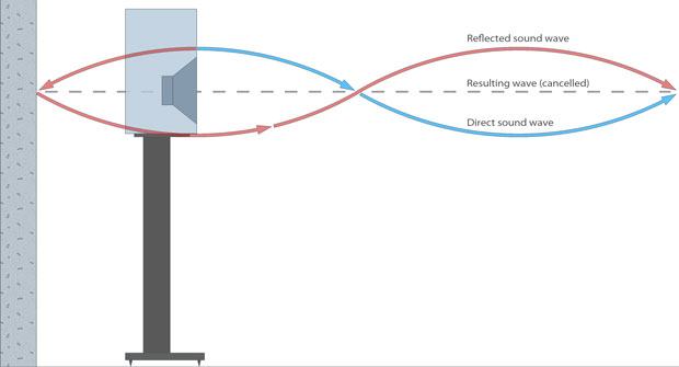
To fully understand the quarter wave design, download MathCad and the MathCad worksheets. They are available for private non-commercial use. Quarter Wave Design In a Transmission Line (I use the term TL for all types of quarter wave designs), the goal most often sought after* is to extend the bass by adding a lift to support the driver. The output from the opening is a desired property of the quarter wave design, and the line should be relatively lightly stuffed.
*[a TL may also be used to create a highly non-resonant enclosure in which the goal is to completely eliminate the back wave of the speaker (ie a desirable goal if you are working with a midrange or a tweeter), and of course there is a continuous spectrum between these two] Problems with TL A TL is a resonant system. The first (lowest) resonance is the one you want. Unfortunately, there are higher resonances as well. These higher harmonics are unwanted, because they cause an uneven sound pressure level with peaks and nulls (ripple). This problem can be minimized by one or all of the following: The geometry of the cabinet (tapered pipe), driver offset down the line and stuffing.